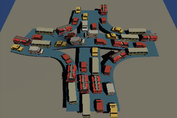
Curves are used in many areas of gaming such as graphics, motion and visual effects. To demonstrate many characteristics of curves, this article will walk you through a project of making a procedural road editor, from the requirements to the thought process and solutions in solving the challenges.
Procedural Road Editor using Curves
Our editor needs to meet these requirements
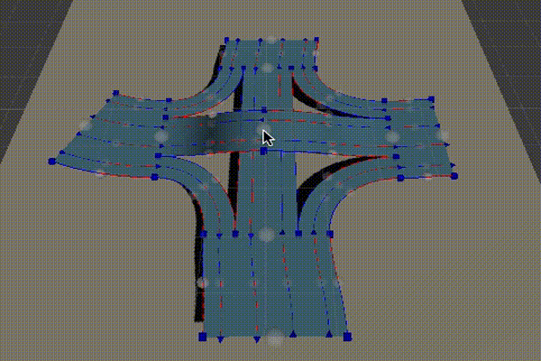
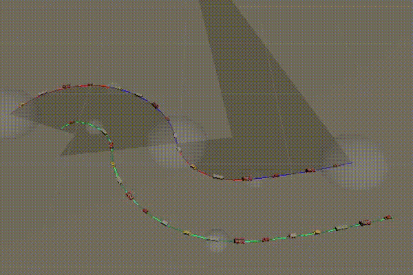
- Able to generate smoothly connected road, i.e. if the player can’t tell where the road pieces are connected. We achieve this by making sure the tangents at the connected point are equal.
- Support elevated roads, such as highways, overpass and bridges.
- Support parallel lanes: lanes need to stay perfectly parallel across the length of the roads
- Authored by control points: road shape and size should be easily adjustable via control points
- Constant vehicle speed: vehicle moves on the road at constant speed, i.e. vehicle’s speed should not be affected by the road curvature. This seems to be a trivial requirement but it’s not. We will see its intricacies later in the article.
- Highly performant: we should aim for the minimal amount of computation so that we can scale up the number of vehicles and roads in our editor
Curve definition
Curve is a function to transform a 1-dimensional coordinate to a position in space (2D or 3D). If we limits the input coordinate to [0, 1], we will have a curve segment. However, most curve functions work with input outside of this [0, 1] range.
Line Segment
Also known as the Linear Bezier, or a Bezier with two control points
Inputs:
public float3 Start;
public float3 End;
Formula:
public float3 Point(float coord)
{
return math.lerp(Start, End, coord);
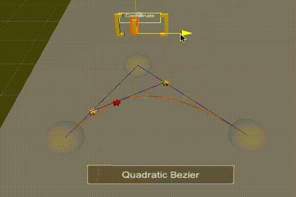
}Quadratic Bezier
Quadratic Bezier has 3 control points A, B, and C. The curve start from A, with tangent AB and end at C, with tangent BC.
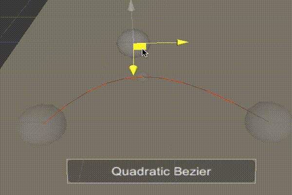
The Quadratic Bezier is constructed by a series of interpolations. The 3 control points A,B & C will interpolate the 2 immediate points M & N (yellow points). And from M & N, we interpolate the final result X (the red point). The code for interpolations is as follow:
public float3 Point(float coord)
{
    var M = math.lerp(A, B, coord);
    var N = math.lerp(B, C, coord);
    return math.lerp(M, N, coord);
}
The formula code is simplified and does not require 3 interpolations.
public float3 Point(float coord)
{
    float t1 = 1 - coord;
    return t1 * t1 * a
        + 2 * t1 * coord * b
        + coord * coord * c;
}
The tangent formula is the derivative of the curve formula.
public float3 Tangent(float coord)
{
float t1 = 1 - coord;
return 2 * t1 * (b - a)
+ 2 * coord * (c - b);
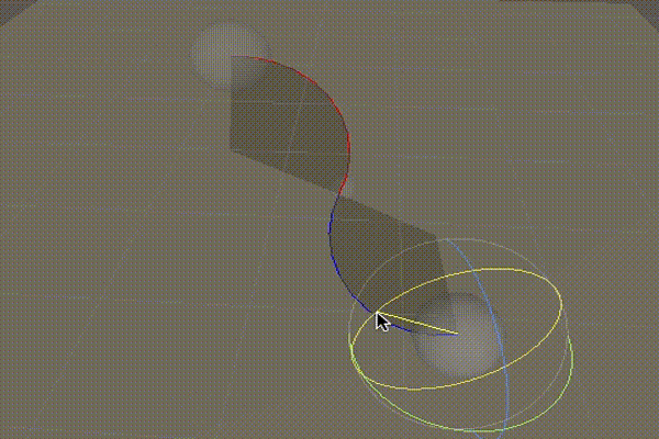
}Cubic Bezier
The Cubic Bezier has 4 control points A, B, C & D. The curve starts at A, with tangent AB and end at D with tangent CD. Inputs:
public float3 a;
public float3 b;
public float3 c;
public float3 d;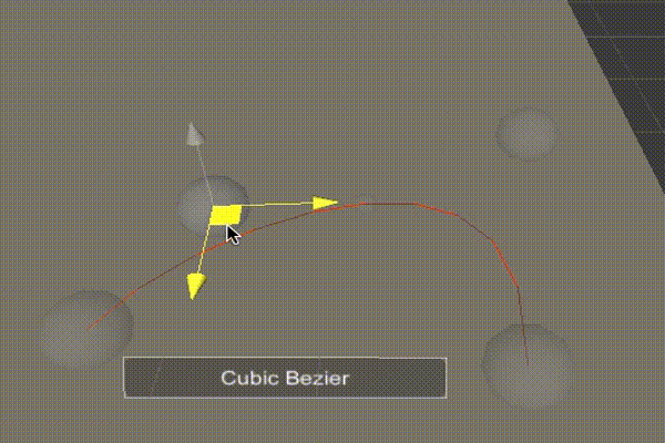
We can construct the Cubic Bezier similarly to the Quadratic Bezier, by using a series of interpolations, i.e from 4 control points, we interpolate 3 intermediate points (yellow), and then 2 (blue), and then the final result (red). With this method, we can build a bezier curve with any number of control points. However, with 4 control points, the Cubic Bezier has enough flexibility to represent most curve shapes. It is the most popular curve which is used in many graphics software.
Curve formula
public float3 Point(float coord)
{
    float t1 = 1 - coord;
    float t12 = t1 * t1;
    float t13 = t1 * t1 * t1;
    return t13 * a
           + 3 * t12 * coord * b
           + 3 * t1 * coord * coord * c
           + coord * coord * coord * d;
}
Tangent formula
public float3 Tangent(float coord)
{
    float t1 = 1 - coord;
    float t12 = t1 * t1;
    return -3 * t12 * a
           + (3 * t12 - 6 * t1 * coord) * b
           + (-3 * coord * coord + 6 * coord * t1) * c
           + 3 * coord * coord * d;
}
Vehicle Speed on Bezier
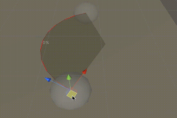
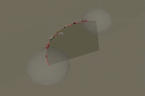
Curve Deviance
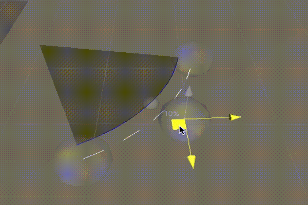
A curve can be divided into a number of segments, by sampling the points at intervals in the coordinate space. For example, the curve can be divided into 4 segments by sampling the points at 0, 0.25, 0.5, 0.75 and 1.
Deviance is a percentage value, represent the ratio between the largest segments and the smallest segments.
Bezier often have deviance larger than 0%, and the value changes depends on how we position the control points. The value of 0% means that all the segments are equal in length. A value of 200% means that the longest segment is 200 + 100 = 300% the length of the smallest segment.
Vehicle Speed
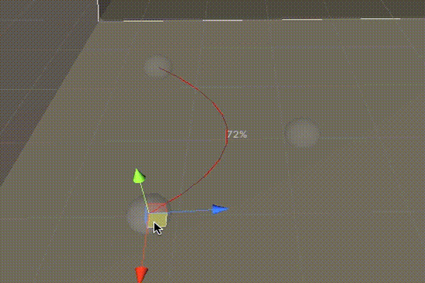
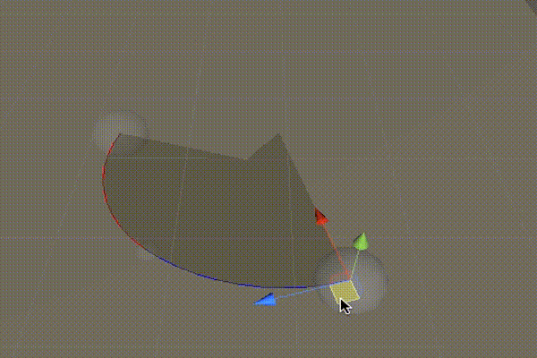
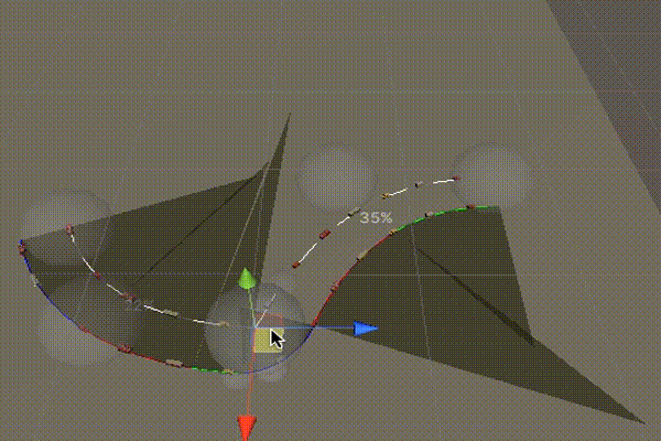
There are many way to move a vehicle along a curve. We could divide the curve into many linear segments, compute these segment’s lengths and move the vehicle along these segment using linear interpolation. This will give the vehicle a constant speed. However, this method is very memory intensive, and expensive to re-calculate all the segment’s length whenever the curve changes.
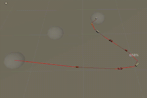
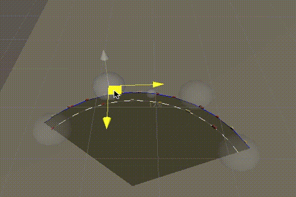
Another way is to move the vehicle along the coordinate space. This only requires to compute the length of the entire curve instead of all the segments. However, if the deviance is not 0%, the speed won’t be constant. The Cubic Bezier curve below has Deviance of 658% and the vehicles move faster at the start and slower toward the point with high curvature near the centre.
Curve Offset
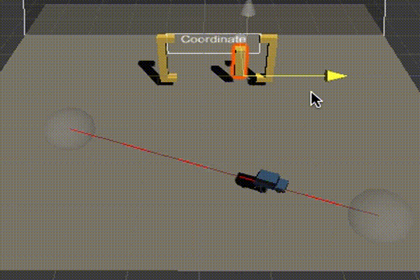
From the vehicle perspective:
- Tangent is where the vehicle is heading
- Up points upward
- Normal is perpendicular to Tangent and Up
public static float3 Normal(this ICurve3D curve, float t, float3 up)
{
    return math.normalize(math.cross(curve.Tangent(t), up));
}
From the Normal vector, we can compute the Offset Point of the curve. An offset curve has the same tangent to the original curve given the same input coordinate. The distance between an offset point and its original is always the same, i.e. the offset curve is parallel with the original curve.
public static float3 Offset(this T curve, float t,
    float3 up, float offset) where T:ICurve3D
{
    return curve.Point(t) + curve.Normal(t, up) * offset;
}
Offsets often change Deviance because some segments get bigger while others get smaller
Offsets of a Linear Bezier is also a Linear Bezier. However, offsets of higher ordered bezier like Quadratic and Cubic Bezier are not a bezier. The cost of calculating an offset is always higher than the original curve in this case.
Curve Length
Except the Linear Bezier, the Bezier family has no formula to compute its length. A good approach would be using recursive binary division to divide the curve into linear segments and sum up their lengths. The recursive division stop when it no longer improve the accuracy beyond a curtain threshold.
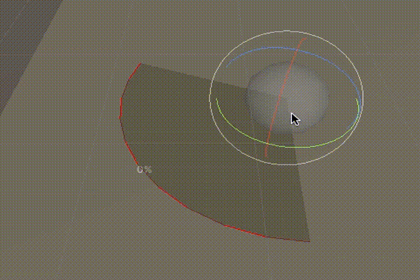
Circular Arc
Circular Arc is a part of a Circle. There are three main ways to construct a Circular Arc
This is how Circular Arc 2D is calculated
public float2 Center;
//clockwise going along Up vector
public float StartAngle;
public float EndAngle;
public float Radius;

public float2 Point(float coord)
{
    float tAngle = math.lerp(StartAngle,
        EndAngle, coord);
    return Center + (new float2(math.cos(tAngle),
        math.sin(tAngle)) * Radius);
}

public float2 Tangent(float coord)
{
    return math.cross(
        (Point(coord) - Center).To3D(),
        EndAngle > StartAngle ? Up : Down
        ).To2D();
}
The 3D version is slightly different
public float3 Center;
public float3 Right; //length equal to Radius
public float3 Forward; //length equal to Radius
public float3 Up; //unit length
//clockwise going along Up vector
public float Angle;

public float3 Point(float coord)
{
    float tAngle = coord * Angle;
    return Center + Right * math.cos(tAngle) +
        Forward * math.sin(tAngle);
}

public float3 Tangent(float coord)
{
    var point = Point(coord);
    return math.cross(point - Center, Up);
}
It’s easy to calculate the length of a Circular Arc
public float Length()
{
    return Radius *
        math.abs(EndAngle - StartAngle);
}
An offset of a Circular Arc is also a Circular Arc, with a different radius.
The Deviance of a Circular Arc is always 0%. This is great for moving vehicle at a constant speed: by simply moving the coordinate at a constant speed.
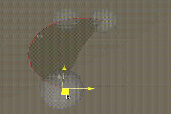
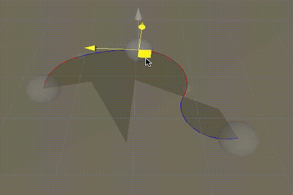
Bi-Arc
A Bi-Arc is a pair of two Circular Arcs that form a continuous curve: the ending tangent of the first arc is equal to the starting tangent of the second arc.
A singular Arc is too limited in representing curvy shapes. The Bi-Arc gave us a level of flexibility close to that of a Cubic Bezier.
Multiple Bi-Arc can be chained together to form a longer and continuous curve. By sharing the middle control point, the ending tangent of the first Bi-Arc will be the same as the starting tangent of the second Bi-Arc.
Because Bi-Arc consists of multiple Circular Arcs, it has 0% Deviance and easy to achieve constant vehicle speed. Notice that the offset also achieve constant vehicle speed because offset of Circular Arc is also a Circular Arc. This is great to model road with multiple parallel lanes.
In some situations the starting tangent and the ending tangent are non-planar, the middle point is twisted and the two normal vectors (toward two arc’s centres) will disconnect. The Bi-Arc itself is still continuous. However, this will cause broken offset curve, to be examined in the Elevated Road section below.
Curve Conversion to Circular Arcs
Both Arcs and Beziers have pros and cons. We want 0% Deviance from Arc and easy authoring from Bezier. The Bezier can be controled simply by moving the control points, while Multi-Bi-Arc need rotation as well.
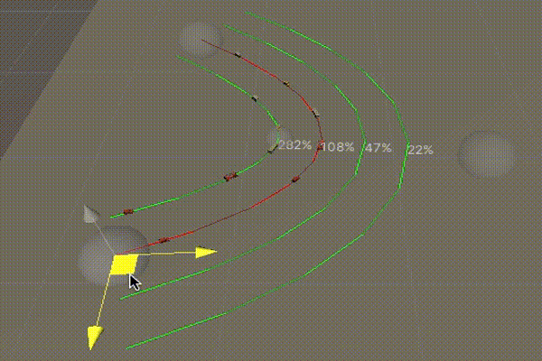
The solution is to convert Bezier (or any curve) into a set of continuous Circular Arcs. We can use recursive binary division to retrofit a Circular Arc (using 3 points construction) on top of the curve. The recursive division stops when the error between the Arc and the Curve is below a certain threshold.
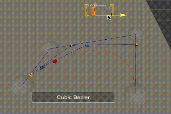
From the example on the right, you can see it starts with one Arc and has to divide to more Arcs when the Quadratic Bezier (rendered in dashed white curve) has its Deviance value increased.
Here is an example of converting Cubic Bezier to Circular Arcs. Notice that the converted curve has constant vehicle speed while the original curve (white) does not.
We can also convert non-continuous curves, i.e. two Quadratic Curve in this example. The resulted curve will smooth out the broken connection between the two original curves.
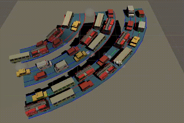
Elevated Roads
At this point, we have two solutions to achieve all our requirements: Bi-Arc and Convert To Arcs. However, roads often consists of multiple parallel lanes, and sometime elevated. Let’s put together a solution for elevated multi-lanes road using what we described so far.
The Left Ramp is constructed by using four Bi-Arcs, two for the lanes and two for the road boundary.
These Bi-Arcs have parallel start tangents and end tangents. However, when inspecting from the top, the road does not have evenly distributed width, which will cause vehicles to overlap.
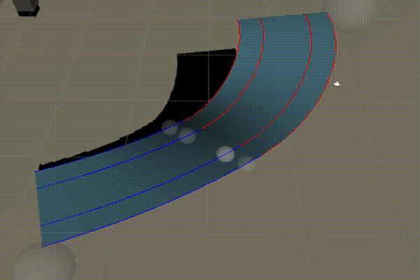
The Middle Ramp is constructed by a Bi-Arc in the centre, and four offsets from it for the two lanes and two road boundaries.
The road looks great in C-shape. However, the road has broken curves when adjusting to S-shape. This is due to the twisting of normal vectors happening in the middle Bi-Arc. The offsets move points along the normal, thus create broken curves.
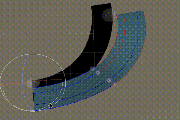
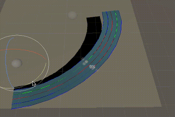
The Right Ramp is constructed by a Cubic Bezier in the middle. Four offsets are calculated from the middle Bezier. Then, we convert these four offsets into Circular Arcs.
This ramp satisfies all the requirements we need. However, it’s more complicated to construct. And the result also have more curves than the other alternatives.
In general, the Middle Ramp is good and more performant in all flat roads, while the Right Ramp is best for elevated roads.
Conclusion
In solving our challenge of creating a road editor, we learned about many type of curves, each has their own pros and cons. I hope that this article would give you some insights into which curve is suitable for your applications.
Some explanations for the columns:
- Control Points: the number of points needed to construct the curve.
- Flexibility Degree: means that the curve can recreate all shapes from any curve with lower Flexibility Degree.
- Length & Intersection Computation: whether we can compute it accurately via a formula, or approximate using binary division.
- Offset Curve: the curve type of its offset.
- Split Into: choose an arbitrary coordinate in [0, 1] to split the curve into two.
- Update Cost: the cost of re-compute the curve when we move the Control Points.
- Twisted: whether the normal change gradually or (potentially) abruptly when we change the input coordinate gradually.
- Deviance: a curve with no Deviance makes it simple to control vehicle speed using input coordinate.
- Chain: whether we can chain multiple of them into a smooth curve.
| Curve | Control Points | Flexibility Degree | Length & Intersection Computation | Offset Curve | Split Into | Update Cost | Twisted | Deviance | Chain |
|---|---|---|---|---|---|---|---|---|---|
| Line | 2 | 1 | Accurate | Line | Lines | Low | No | No | No |
| Quadratic Bezier | 3 | 3 | Approximate | Not a bezier | Quadratic Beziers | Low | No | Yes | Yes |
| Cubic Bezier | 4 | 4 | Approximate | Not a bezier | Cubic Beziers | Low | No | Yes | Yes |
| Circular Arc | 3 | 2 | Accurate | Circular Arc | Circular Arcs | Medium | No | No | No |
| Bi-Arc | 4 | 4 | Accurate | Bi-Arc | Circular Arcs | Medium | Yes | No | Yes |
| Convert- To-Arcs | >=2 | 5 | Accurate | Set of Arcs | Circular Arcs | High | Yes | No | Yes |